Creating & Comparing Bounding Geometry
Included in this tutorial:
Minimum Bounding Geometry: line feature inputs and point feature inputs, with examples
Concave Hulls: point feature inputs only
Alpha Shapes
K-Nearest Neighbors
Software version in examples: QGIS 3.26.2
Tutorial Data: The tutorial includes demonstration with sample data available here.
Credits: L. Meisterlin (2022)
This tutorial compares different tools for creating bounding geometry polygons within the QGIS Processing toolbox.
The tools included are all contained in the Vector geometry toolset. They are Minimum Bounding Geometry, Concave Hull (alpha shapes), and Concave Hull (K-Nearest Neighbors).
Minimum Bounding Geometry
For generating minimum bounding polygons from line or point features, use the Minimum Bounding Geometry tool.
The Minimum Bounding Geometry tool generates polygons enclosing the features within the input layer. Options include:
Selected features only (checkbox): Limits the algorithm to include only selected features within the input layer.
Field: Choose a field in the input attribute table to group input features, and thus generate multiple output boundary polygons (one per group).
Geometry Type: There are four options. These are compared below.
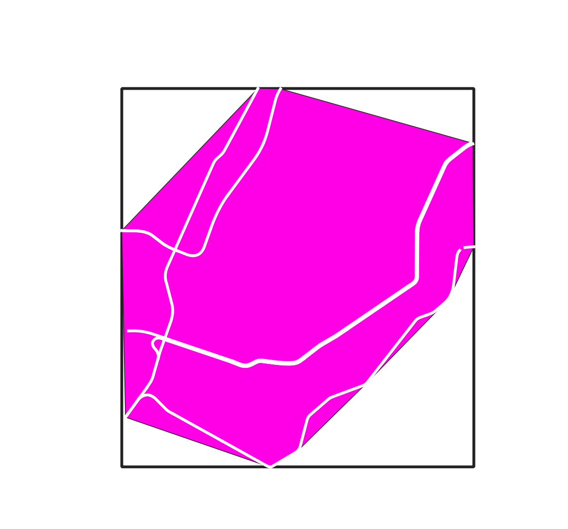
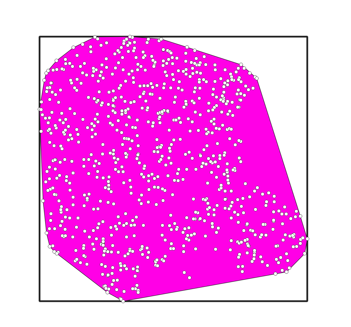
A comparison of the four geometry type options is below. For each, the input layer is represented in white, with the output bounding geometry in magenta. The boundary of the Bounding Box Envelope is shown in all outputs for context and scale.Bounding Geometry (Output): Choose whether to generate a temporary layer or save it by specifying the type, location, and name). Choose also whether the output should be added to the current map project with the Open output file after running algorithm checkbox.
Line Feature Input examples


Point Feature Input examples


Concave Hulls (Point inputs only)
Alpha Shapes
Use the Concave Hull (alpha shapes) to produce a boundary polygon when the others above capture more area than your input features reasonably cover.
The additional options of this tool include
Threshold: this value (between 0 and 1) indicates the acceptable level of concavity. A smaller number indicates greater concavity. A value of 1 generates a convex hull.
The examples below show the impact of different threshold values, with the bounding box envelope for comparability.Toggle options include allowing holes or splitting multipart geometries into single parts.


K-Nearest Neighbors
Use the Concave Hull (K-Nearest Neighbors) tool to produce concave hulls based on the location of neighboring features surrounding each input feature.
The additional options of this tool include the number of neighboring points to consider. Considering more points will create a smoother boundary; considering fewer will result in greater concavity.
The examples below show the impact of different K values, with the bounding box envelope for comparability. (For your reference, there are 800 features in the input layer.)


